Having been rather addicted to understanding electronics lately, I’m always looking for something to play with. Last week I was about to throw out a broken wireless Microsoft mouse, but I caught myself and ended up taking it apart.
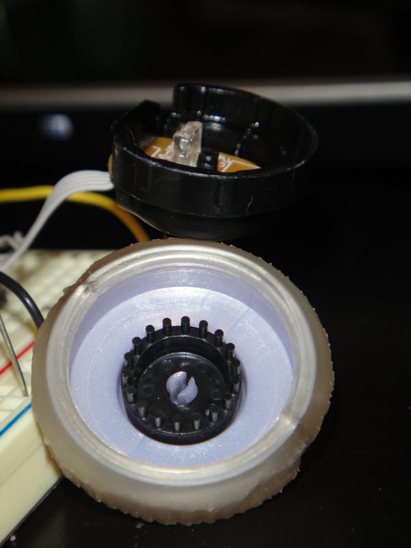
I dug down to the scroll wheel and found out it was a nice little rotary encoder – there’s an LED pointed at two phototransistors (light detectors) in it, as well as a circle of tiny black posts that pass between the LED and the detectors, as you can see to the left. When the posts pass in front of the detectors, the Arduino reads them and is able to determine which direction they are going and increments or decrements a variable that I can access.
It took me about 4 hours to figure out how to hook this thing up, so I figured I would share the info in case someone else wants to use a rotary encoder from a Microsoft mouse in their project.
If you are holding the encoder so that the rotating half is facing you and the wires are facing down, the pinout is as follows:
Pin 1: Photo Sensor 1
Pin 2: Vcc
Pin 3: Photo Sensor 2
Pin 4: IR LED +
Pin 5: IR LED -
Unlike most of the examples I found for using a rotary encoder, this one requires +Vcc on Pin 2 – power will not flow the other way. The LED power is very picky too; I am powering it from the 5v regulated supply on my Arduino through a 1k resistor to keep the right amount of light in the encoder. Too much light and both sensors will be high for too long and too little, neither will go high. The hardest part to figure out was the voltage divider circuit for the sensors. I could get them working ok on an analog input – swinging between about 80-600, but it wasn’t clean enough to input as digital until I found the right resistor: 10k. This nicely divides the input between ground and +5v so the encoder can be read.
Here is the Arduino sketch for the project as shown in the video above:
// and SparkFun 4 Digit Serial 7-Segment Display
// by Steve Kamerman 12/18/2010
// http://www.stevekamerman.com/2010/12/understanding-a-mouse-scroll-wheel/
// These MUST be on interrupt pins!
#define encoderPinA 2
#define encoderPinB 3
#define displayTXPin 10
#define displayRXPin 11
// used only for sprintf()
#include <stdio.h>
// If you don't have NewSoftSerial, grab it from:
// http://arduiniana.org/libraries/NewSoftSerial/
#include <NewSoftSerial.h>
NewSoftSerial displaySerial(displayRXPin, displayTXPin);
// the value - this must be volatile because it is modified
// during an interrupt function and used in a normal function
volatile unsigned int encoderPos = 0;
void setup() {
// setup the encoder
pinMode(encoderPinA, INPUT);
pinMode(encoderPinB, INPUT);
attachInterrupt(0, readEncoderA, CHANGE);
attachInterrupt(1, readEncoderB, CHANGE);
// setup the display
pinMode(displayTXPin, OUTPUT);
displaySerial.begin(9600);
// reset display
displaySerial.print("v");
// Set display brightness
displaySerial.print(0x7A, BYTE);
displaySerial.print(0x05, BYTE);
// set the display to " 0"
displaySerial.print("xxx0");
}
void loop(){
displayNumber(encoderPos);
}
// prints the given number, right justified padded with spaces
// sprtinf() is not a great idea if you want to save space
// but I'm really not too worried about it :)
void displayNumber(int num){
char buf[4];
sprintf(buf, "%4d", num);
displaySerial.print(buf);
}
void readEncoderA(){
if (digitalRead(encoderPinA) == HIGH){
encoderPos += (digitalRead(encoderPinB) == LOW)? 1: -1;
}else{
encoderPos += (digitalRead(encoderPinB) == HIGH)? 1: -1;
}
}
void readEncoderB(){
if (digitalRead(encoderPinB) == HIGH){
encoderPos += (digitalRead(encoderPinA) == HIGH)? 1: -1;
}else{
encoderPos += (digitalRead(encoderPinA) == LOW)? 1: -1;
}
}
« Home Temperature Monitor Keep oom_killer from killing your server! »


For the 10K resistor, is that attached to pin 2 or pin 1/3?
Thanks!
There are two 10k resistors. First, connect pin 1 directly to arduino input 2, then put the 10k from ground to input 2. This creates a voltage divider since pin 1 will be slightly positive and the resister will pull it slightly towards ground. Repeat for the other encoder output – pin 3 to input 3, 10k from ground to input 3. Let me know how it turns out!
Excellent. I’ll test it out in a couple of days. I’ll keep you posted of the results.
Tested it out and it works perfectly! Thanks for the great write up.
Hi, quick question. You said there was a 1K resistor; is that between the 5V regulated and VCC?
Also, could you provide a circuit diagram for the whole thing? I’m not too experienced so a visual would really help
Hi JF! I don’t have a diagram, but if you look at the video maximized, at 720p and pause it you can get a pretty good view of what’s going on.
Basically there are two parts:
1. You need a wire from your 5VDC (this is called Vcc) to a 1k resistor (to limit the current/power) to the positive lead on the LED, then connect the ground lead of the LED to ground. This is very simple circuit that does nothing but turn the LED on inside the rotary encoder. If you can take yours apart you probably can’t see the light because it’s probably infrared. If you can see the light but it’s very dim, it’s probably getting way too much power. The 1k I mentioned here is the one you were asking about. This is the entire first circuit.
So far we have an LED shining (circuit 1), now we need the two detectors that detect that light (circuit 2). As we pass an object between the LED and the detectors, first one LED is blocked, then the other. Because of this Right-then-Left or Left-then-Right concept, the program is able to determine which way the object is moving in front of detectors and at what speed.
2. The second circuit is the pair of detectors. These detectors are phototransistors, which are meant to turn on (allow electricity to flow) in the presence of light and turn off in the dark. They are not exactly switches, they just let a lot more power through when it’s light and a lot less when it’s dark. We need to take this signal and feed it into the Arduino in such a way that when there is light, the voltage is about 3v or more, so the digital input is HIGH (1), then when it’s off the voltage needs to be relatively low, like 1v, which is LOW (0). This way the Arduino sees it as a simple on/off switch and is easily able to tell its state. The 10k resistors create something called a voltage divider; without them the the voltage when off was like 4v and when on it was like 4.2v, so it was always high. You can simply use a resistor to pull it all down near the 3v mark because it’s so close to both HIGH and LOW that it behaves erratically. A voltage divider pulls the power at both ends, so when it’s LOW it goes very low, and when it’s HIGH it goes very high, creating a clear seperation. Let me know if you need more info on this.
Hello Steve, I’m also working on a mouse scroll wheel and for mine, it is a mechanical encoder like this one:
industrial.panasonic.com/www-data/pdf/ATC0000/ATC0000CE20.pdf
The scroll wheel in the mouse has typically 3 pins. One is the COM (ground), the other is the A and B that determines the quadrature encoding and its body itself should be connected to Vcc (+5V).
And I’ve got to work it also like on your project that it increases when scrolled clockwise and decreases when scrolled counter-clockwise.
I hope you read this one immediately since I’ve got to work on it a week or less. Thanks for your kind help.
Hi Clarence, this is interesting indeed, but what is your question?
I’m working also with like this one, and mine was I’m using a mechanical encoder from a mouse scroll wheel. It only have 3 pins (COM(ground), A and B), and its body is the Vcc (+5V).
My question is, how will I integrate my mechanical encoder from your program, as if I’m going to print on the Serial Monitor only?
Thanks.
And Steve, this is what I did… I modified some of yours but it doesn’t count. Instead, when it is turned 1 detent, it counts continuously almost a millisecond fast… Then at another detent, the count stops for a number, another detent, continuous count, another detent, it stops…
————————————
/*
Quadrature Example
*/
int encoderPinA = 2;
int encoderPinB = 3;
#include
volatile unsigned int encoderPos = 0;
void setup() {
// setup the encoder
pinMode(encoderPinA, INPUT);
pinMode(encoderPinB, INPUT);
attachInterrupt(0, readEncoderA, CHANGE);
attachInterrupt(1, readEncoderB, CHANGE);
Serial.begin(9600);
}
void loop(){
Serial.print(“Count: “);
Serial.println(encoderPos, DEC);
}
void readEncoderA(){
if (digitalRead(encoderPinA) == HIGH){
encoderPos += (digitalRead(encoderPinB) == LOW)? 1: -1;
}else{
encoderPos += (digitalRead(encoderPinB) == HIGH)? 1: -1;
}
}
void readEncoderB(){
if (digitalRead(encoderPinB) == HIGH){
encoderPos += (digitalRead(encoderPinA) == HIGH)? 1: -1;
}else{
encoderPos += (digitalRead(encoderPinA) == LOW)? 1: -1;
}
}
————————————————-
And by the way, I’ve got to have the right program for mine, but it seems the encoding program needs debouncing, since it gives indefinite counts…
————————————————-
#define encoder0PinA 2
#define encoder0PinB 3
volatile unsigned int encoder0Pos = 0;
void setup() {
pinMode(encoder0PinA, INPUT);
digitalWrite(encoder0PinA, HIGH); // turn on pullup resistor
pinMode(encoder0PinB, INPUT);
digitalWrite(encoder0PinB, HIGH); // turn on pullup resistor
attachInterrupt(0, doEncoder, CHANGE); // encoder pin on interrupt 0 – pin 2
Serial.begin (9600);
Serial.println(“start”); // a personal quirk
}
void loop(){
// do some stuff here – the joy of interrupts is that they take care of themselves
}
void doEncoder() {
/* If pinA and pinB are both high or both low, it is spinning
* forward. If they’re different, it’s going backward.
*
* For more information on speeding up this process, see
* [Reference/PortManipulation], specifically the PIND register.
*/
if (digitalRead(encoder0PinA) == digitalRead(encoder0PinB)) {
encoder0Pos++;
} else {
encoder0Pos–;
}
Serial.println (encoder0Pos, DEC);
}
/* See this expanded function to get a better understanding of the
* meanings of the four possible (pinA, pinB) value pairs:
*/
void doEncoder_Expanded(){
if (digitalRead(encoder0PinA) == HIGH) { // found a low-to-high on channel A
if (digitalRead(encoder0PinB) == LOW) { // check channel B to see which way
// encoder is turning
encoder0Pos = encoder0Pos – 1; // CCW
}
else {
encoder0Pos = encoder0Pos + 1; // CW
}
}
else // found a high-to-low on channel A
{
if (digitalRead(encoder0PinB) == LOW) { // check channel B to see which way
// encoder is turning
encoder0Pos = encoder0Pos + 1; // CW
}
else {
encoder0Pos = encoder0Pos – 1; // CCW
}
}
Serial.println (encoder0Pos, DEC); // debug – remember to comment out
// before final program run
// you don’t want serial slowing down your program if not needed
}
—————————————————–
HI Steve,
I’m loving your blog!
I am a complete Electronics Newb, but I have always been fascinated. I have a little home project on the go at the moment and basically need to control a stepper motor with a rotary encoder. Something like your mouse scroll wheel would be perfect. I want to be able to mirror the revolutions of the encoder on the motor i.e. 1 turn of the encoder = 1 turn of the motor (it is going to remotly control a swivelling platform).
In order to make the prototype I am trying to acquire the components that I will need. I have ordered an Arduino Uno and breadboard, some resistors and a stepper motor – I was hoping to use an old microsoft mouse like in your example.
Is there anything I am missing?
Sorry for such a helpless message!
thanks in advance,
Craig.
Hi Craig – thanks!
You should not drive high current or really noisy devices directly from the Arduino because it will destroy the CPU (the digital outputs are actually coming straight from the CPU itself). Examples: LEDs, traditional light bulbs, motors (steppers are exceptionally noisy), electromagnets, etc.
The solution is to use a “driver” circuit that takes power directly from your power source (bypassing the Arduino circuits), and using the Arduino digital outputs, drives the device. In your case you need a stepper motor driver (unless there’s already one built onto your stepper) – something like this should work: http://www.sparkfun.com/products/10267. I haven’t used steppers (I’m a newb as well), but it looks like the input for this driver uses Pulse Width Modulation (PWM), which means the digital signal is pulsing between high (probably +5VDC) and low (much lower, maybe +1VDC) a variable rate, and by adjusting this rate, you adjust the position of the stepper motor. A seemingly complete example is here: http://bildr.org/2011/06/easydriver/.
The rotary encoder can certainly be salvaged from an existing device, like a mouse – buy you’ll need to figure out the right voltage and stuff for it by hand (unless you can plug it in to your computer and test it). If you have to test it by hand, you should take it apart and see if you can touch the IR LED. Since it’s IR you can’t really tell if it’s on (unless you have a nightvision mode video camera or something). If you can see visible light coming from it, of if it’s generating any heat, turn it off immediately – there’s too much power. Either the voltage is too high or you need a current-limiter (low Ohm resistor) to keep the LED from pulling too much current.
Anyway, feel free to give me a shout if you need a hand figuring it out.
Thanks,
Steve
hola, escribire ne español ya que no soy bueno con el ingles,
Craig, en los sitemas medios , o grandes se usa, motor steper + encoder, pero ne los pequeños, no es necesario.
y que el estper trabaja por paso fijos. significa que dándole una cantidad de pasos se puede predecir donde esta. sin tener que tomar una muestra de su pocicion. esto es verdad simpre y cuando este bien dimensionado , la fuerza del motor y la carga que debe mover. ya que si la carga es mayor de lo que es capaz de mover el motor en el tiempo que se lo pedis “perdera pasos”
post sin corregir las fatas de ortografías, perdon. el encoder se suele usar en sistemas a los que genéricamente se lso llama “servos” es decir que sus motores puede ser de CC, de AC. o los brush lees, donde no hay una relación sincrónica entre la excitación y el movimiento del eje.
para mover un motor coincido con steve, usar un driver como los que recomendó para que el arduino solo se dedique a generar las señales de control. si están experimentando recomiendo tratar una cosa a la vez, poner énfasis en el motor o en el encoder, no en los dos simultáneamente, a pesar que hacen falta ambos para probar cualquiera de los dos.
los estepper son fáciles de manejar, hay driver baratos, no tiene mucha velocidad ni mucha fuerza, una vez que ya podes colocar el eje donde quieres a la velocidad que quieres, (dentro de los limites del conjunto) entonce colocar en el eje del esteper un encoder, y así sabrás si el encoder esta leyendo correctamente, ya que una de la fallas típicas es que pierdan algunas cuentas, o que cuenten 10 pulsos cuando solo tenían que contar 4, y si no tienen un eje que saben exactamente donde esta posicionado les resultará imposible saber quien “miente”. una diferencia muy importante en los encoder de cuadratura mecánicos y ópticos, es que los mecánicos introducen “ruido” y esto altera la cuenta, le suma mas de lo que en realidad hay. MOUSER tiene algunos encoder mecanices de 2 dolares , y 30 pulso por revolución que se pueden usar par empezar. la solución para estos suele ser una mezcla de soft y de filtros de hardware, resistencia y capaciotres. +un smit triger en cada linea A, B. como el CD40106B, de 0.44USD/ud. espero que estos comentarios los oriente en la solución y experimentación con motores y encoder.
como dice un amigo ” divide y reinaras” suerte.
Brilliant idea! Want to try this one out when I have time this weekend. I have several mouse with me that I haven’t thrown yet. If this works this can be so helpful. Thank you for sharing this wonderful post.